
Framing for Storage
When storage becomes a cabinet, shelving unit, workbench, or freestanding support, the structure itself becomes part of the design. Combine aluminium profiles, round shafts, panels, and connectors to build a structure sized around the space and the objects.
Framing here describes a construction approach. It does not classify round shafts as aluminium profiles.
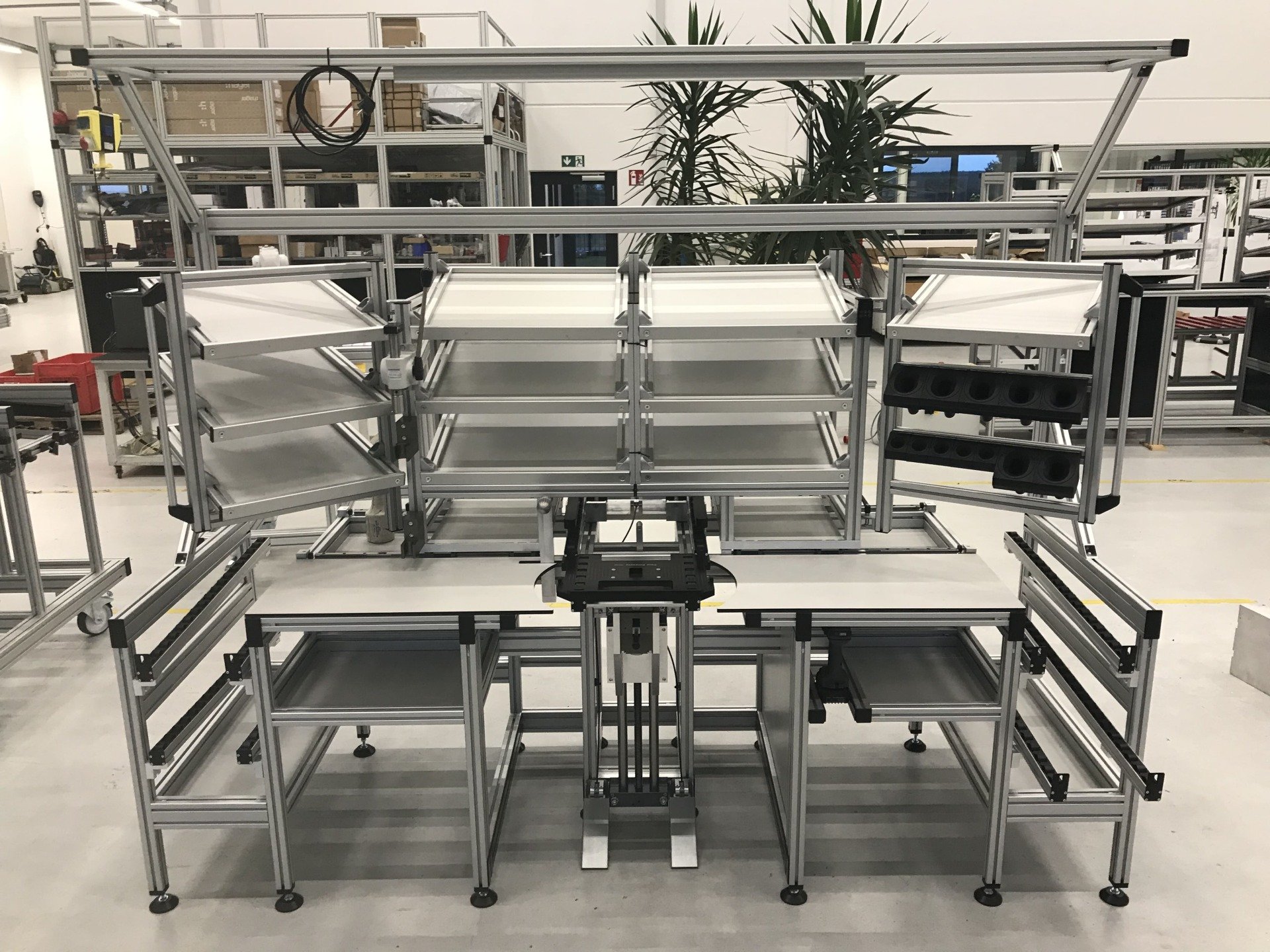
Reference example: ERWEMA's item profile applications. The photograph illustrates a frame working with other storage components, not a completed RONZ project. It does not establish the exact profile model shown.
Aluminium profiles and round shafts use different interfaces
Aluminium profiles
Slotted aluminium profiles connect through grooves, nuts, and fittings to form frames, support panels, and carry accessories. Do not choose solely by names such as 2020 or 4040: profiles of the same overall size can have different grooves and internal geometry.
Check cross-section width and height, groove opening, internal mating dimensions, centre bore, connector series, and whether the ends need tapping or other machining.
For example, item's Profile 8 40×40 E drawing specifies a 40 mm square cross-section and an 8 mm groove opening. It describes this model, not a universal interface for all 40×40 profiles.
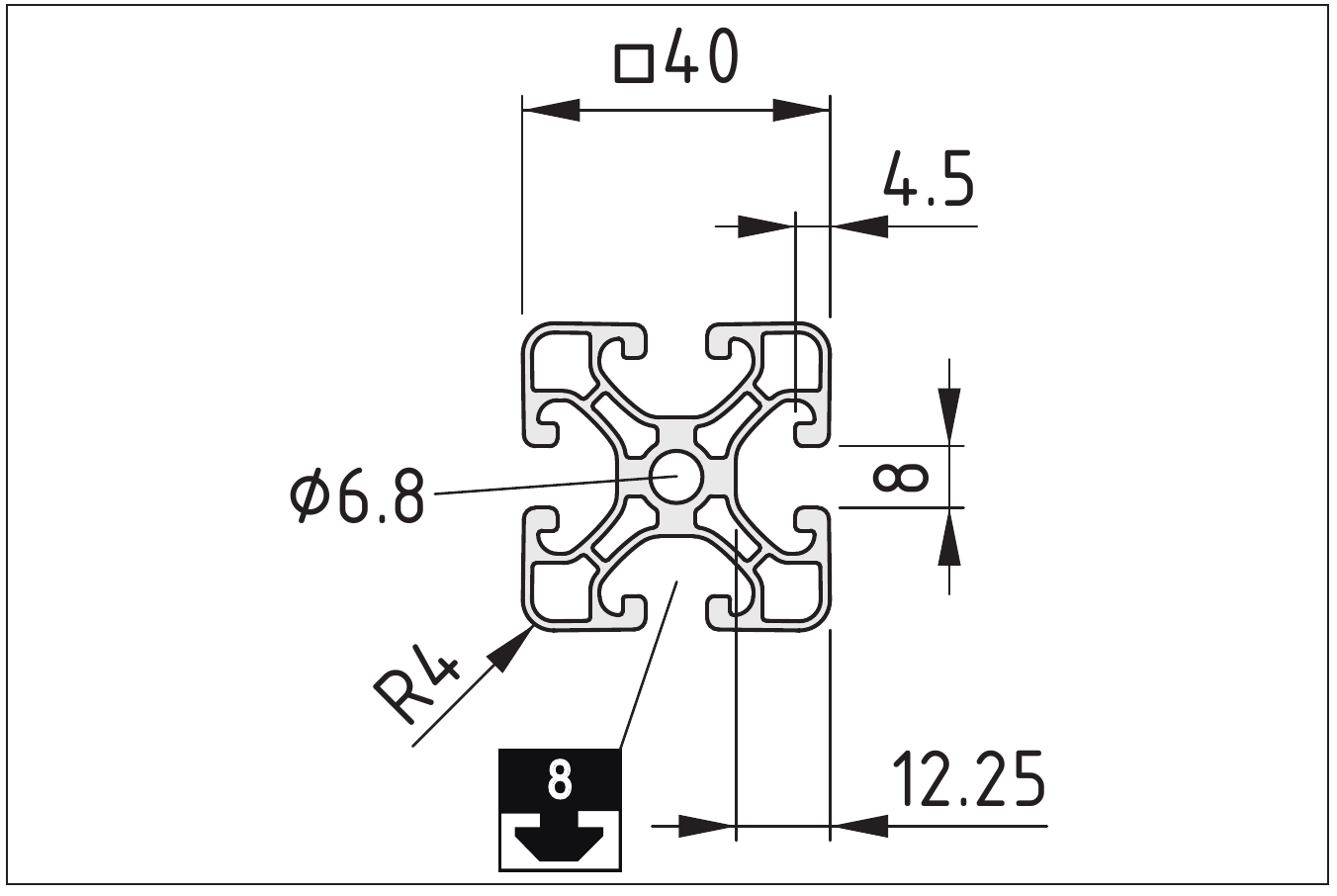
This section is taken from the technical sheet for item model 7.0.000.09, preserving the original outline and dimensions rather than replacing the actual interface with an invented simplification. Check both the groove series and overall dimensions; 4040 alone is not enough to select connectors.
Round shafts
A round shaft is defined primarily by its diameter, clamps, and end connections. In a suitable structure it can form a crossbar, hanging rail, or mounting carrier for accessories.
Check diameter and tolerance, material, finish, clamping length, fixing method, and support span. An 8 mm nominal diameter alone does not establish that two clamping fits are the same. MISUMI's shaft-selection information also distinguishes outside-diameter tolerances and mating components.
The fitting requirements for static storage clamps are not the same as bearing fits for precision linear motion. Round-shaft storage does not automatically imply a moving mechanism.
Frames, panels, and accessories have distinct roles
Frames provide structure and mounting positions. Side panels, shelves, and doors create the usable surfaces; pegboards, drawers, and holders organise the objects. Marine plywood is one possible panel material, but its name alone does not specify thickness, construction, finish, or suitability for the environment.
| Component layer | What to check first |
|---|---|
| Main frame | Overall dimensions, span, cross-section, joints, and lateral bracing |
| Shafts or crossbars | Diameter, clamping interfaces, support points, and positions |
| Panels and shelves | Thickness, span, fixing points, and surface requirements |
| Drawers and doors | Clearances, slides, and opening interference |
| Feet, castors, or wall fixings | Support method, stability, and resistance to tipping |
| Accessories | Compatibility with frame interfaces and object shapes |
Larger sections or thicker panels do not automatically make the complete structure safe. Joints, deflection over long spans, lateral stability, concentrated loads, and the installation environment need verification within the actual design. Do not assign a universal load rating to an unverified structure.
Work back from what the structure must hold
Record the largest objects and the direction in which they need to be taken out. Then determine clearances, openings, shelf levels, and support positions. Panel thickness, slides, and connectors take up space; cabinet outside dimensions are not its usable inside dimensions.
The structure can coordinate with the other systems: a cabinet can contain Gridfinity drawers, its sides or back can support pegboards, and suitable holders can support heavier objects. Not every item needs to hang on a thin panel.
You can build it; RONZ provides plans and options
RONZ aims to provide clear structural plans, interface definitions, and material lists. Source and assemble the parts yourself, or choose a material kit cut and prepared for the plan, together with designed connectors and accessories.
A kit should clearly list cut lengths, end machining, panel dimensions, hardware quantities, and assembly order. Custom dimensions mean making the interfaces work in actual materials, not merely changing a rendering.
The products, plans, and validation scope are defined by the actual deliverables offered.